An Actual "Hello, World!" for Microcontrollers (in Rust!)
Over the past few months, I’ve become interested in learning how to program embedded devices, especially in Rust. I’ve been drawn in by the idea that I can connect off-the-shelf components to build physical systems. I’m also one of those people that’s convinced that Rust is the future with it’s type system and memory safety, two aspects that I think will greatly benefit all low level systems.
Even though there’s a bunch of useful information and tutorials available, embedded software is a GIANT and DIVERSE area of programming. Unlike web development (which I do for my day job), embedded software spans many different types of processors, microcontrollers, communication protocols, and peripherals. It requires knowing how to correctly compile for your intended architecture, how to use gdb to debug (and maybe semihosting to use good old print statements), and how to read reference manuals for your microcontroller; using npm isn’t nearly as difficult!
That’s all to say that I’ve been pretty out of my comfort zone learning embedded programming. Something that was lacking for me though was a satisfying “Hello, World!” introduction. As you may know, you can’t really “print” things on embedded devices. There’s no screen on a microcontroller. There’s (probably) not a file system, so you can’t redirect logging to a file. You can use semihosting for logging to your computer, but that’s not really the intended use of a microcontroller (I do want to accomplish more than just debug). The “Hello, World!” of MCUs is blinking a light on your board, which serves the intended purpose of creating a simple program to spark further interest.
Therefore, this post isn’t really about replacing the blinking light program, but more an exploration of how one could go about printing “Hello, World!” using a microcontroller. So I decided to buy an LCD screen to accomplish this task. This post will show how to initialize and use the I2C protocol on a microcontroller to communicate with an LCD screen, but only using the primatives available in the corresponding HAL crate. I will be using an STM32F303DISCOVERY board and a 16x2 LCD screen that supports I2C (they should all have the same Hitachi HD44780 microcontroller). I’ve made the code available here so that you can follow along.
Before going any further, this post isn’t meant as an introduction for absolute beginners of microcontroller programming. I’m assuming you understand how a microcontroller works (at a very high level). If you’re new to microcontrollers, I recommend checking out the Rust Discovery book and going through the examples there.
Brief I2C overview
There are a few different protocols we could use to connect our microcontroller to an LCD. I decided to go with I2C (for no particular reason other than it can be done). I2C only requires two wires (besides the ones for power), one for the Serial Data Line (SDA) and the other for the Serial Clock Line (SCL):
- SDA: carries the data between master and slave devices
- SCL: provides the timing mechanism so each device knows when to sample the SDA
I won’t go into much more detail about I2C as others have already made detail explanations, but it’s important to note that I2C uses addresses to communicate with the correct device; later on, we will need to find out the address of the LCD so that we can communicate with it (this means that I2C supports multiple masters and multiple slaves on the same bus).
Connecting the components
Connecting the microcontoller and LCD requires four wires: one for SDA, one for SCL, one for power (VCC), and one for ground (GND). For power, connect the VCC wire into the correct power supply pin on your microcontroller (mine uses 5V) and connect the ground line into a GND pin (there might be multiple GND pins, any will do). That was easy enough, but what about the pins for SDA and SCL? Time to read some manuals!
Aside: There are three different manuals that you might need: User Manual, Reference Manual, and Data Sheet. I would say the best place to start is the User Manual, it usually gives the high level view of what you want, then you can go splunking in the Reference Manual or Data Sheet. Honestly, I frequently have trouble finding things and end up using a lot of ctrl-f to get what I need.
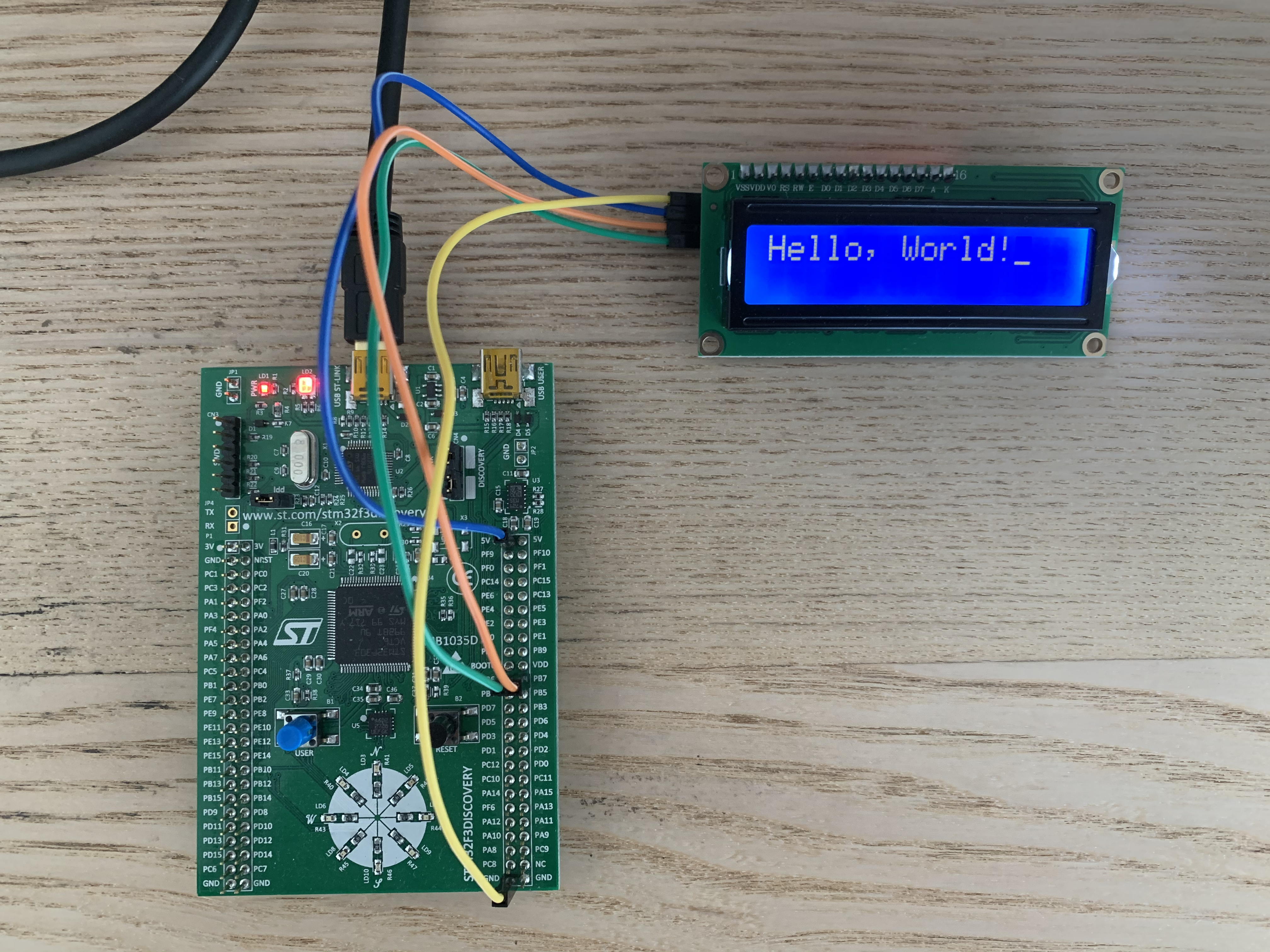
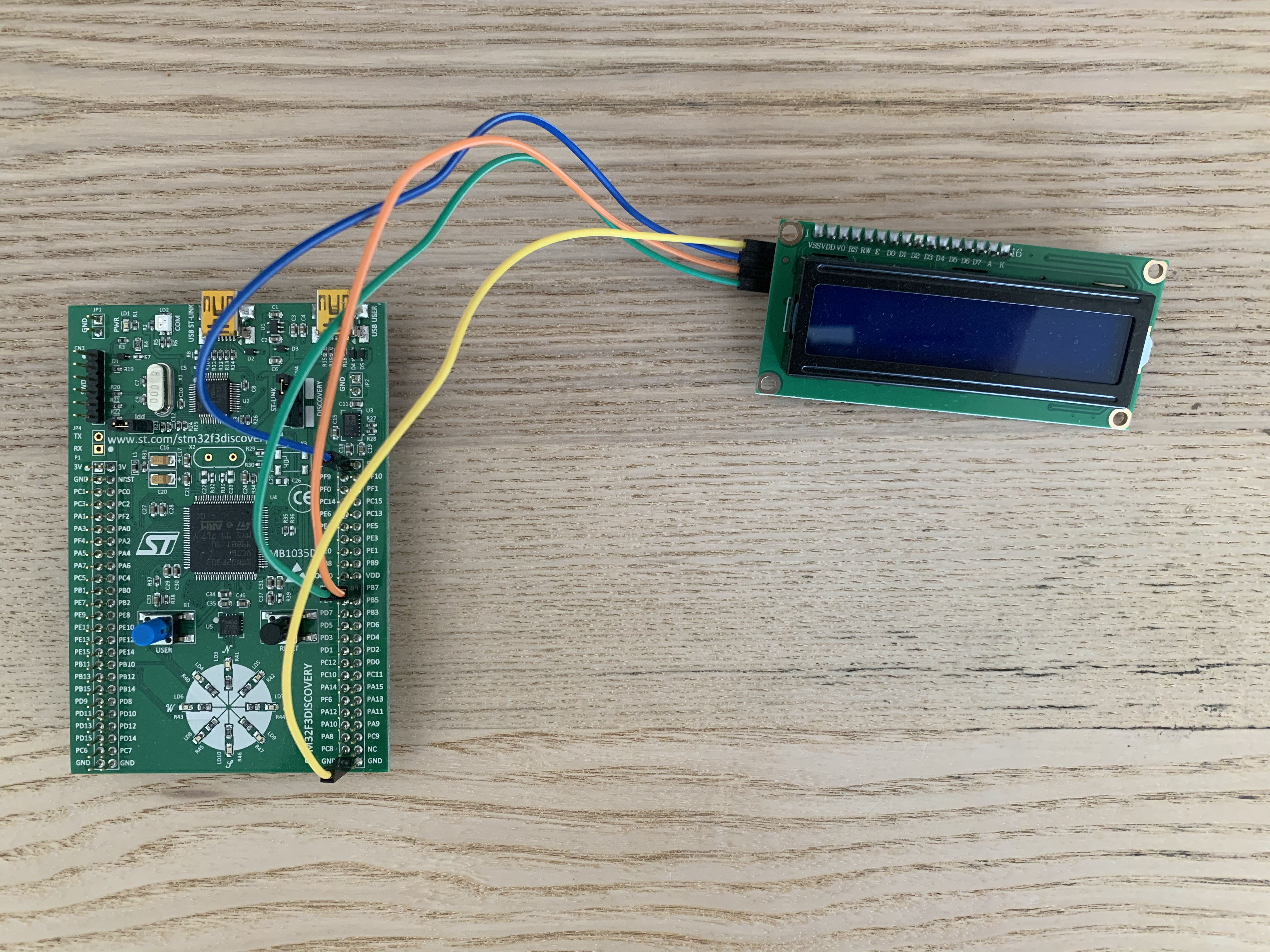
Ok, back to the task of finding the correct pins for SDA and SCL. I2C is an “Alternate Function” for some pins; certain pins support I2C, but these pins are not configured for I2C communication by default. On page 26 of the User Manual, we see that PB6 and PB7 can be used for SCL and SDA respectively, so we just need to connect the SCL wire into PB6 and the SDA into PB7. And that’s it! Your connections should look something like this:
Board and I2C initialization
Now that we’ve connected the board, we arrive at the meat of the task. Disclaimer: a good chunk of the nitty gritty details still go over my head, so I may be a bit handwavy with explanations. With the help of the reference manual, the stm32fxx_hal crate, and the Rust embedded Discovery code repository, I’ve been able to compile a working “Hello, World!” example. But before we can make the LCD screen dance, we must set the stage. That’s to say we need to initialize the I2C connection. Below is the snippet that does this.
use cortex_m_rt::entry;


use stm32f3xx_hal::prelude::*;
use stm32f3xx_hal::{self, delay, pac, i2c, stm32};

...

#[entry]
fn main() -> ! {
    let dp = pac::Peripherals::take().unwrap();

    let mut flash = dp.FLASH.constrain();
    let mut rcc = dp.RCC.constrain();

    let clocks = rcc.cfgr.freeze(&mut flash.acr);

    let mut gpiob = dp.GPIOB.split(&mut rcc.ahb);

    let scl = gpiob.pb6.into_af4(&mut gpiob.moder, &mut gpiob.afrl);
    let sda = gpiob.pb7.into_af4(&mut gpiob.moder, &mut gpiob.afrl);

    let mut i2c = i2c::I2c::i2c1(
      dp.I2C1,
      (scl, sda),
      400.khz(),
      clocks,
      &mut rcc.apb1
    );
Yup, that’s all we need to do to initialize the I2C connection. It’s pretty dense, so let’s take it line by line to see if we can make some sense of it.
    let dp = pac::Peripherals::take().unwrap();

    let mut flash = dp.FLASH.constrain();
    let mut rcc = dp.RCC.constrain();
Before we do anything, we need to get access to all the peripherals. Using take() and unwrap() may seem odd, but the rust HAL crates adhere to the singleton pattern for peripherals. The Embedded Rust Book goes into much greater detail as to why this pattern is used, but the main idea is that once you’ve moved a peripheral with take(), you can’t take() it again, therefore preventing data races and inconsistencies that could arise from multiple instances of a peripheral floating around in your code. Calling constrain() on both FLASH and RCC similarly moves the flash memory and reset and clock control peripherals. We can’t call constrain() again on either, as the ownership of these two structs has been moved.
let clocks = rcc.cfgr.freeze(&mut flash.acr);
Before clock initialization, one can set the frequencies of the system clock and the clock on some buses. Calling freeze() on the clock configuration finalizes the different clock speeds. But why do we need to pass in &mut flash.acr? In the stm32f3xx_hal crate source, there’s a comment that says
// Adjust flash wait states according to the
// HCLK frequency (cpu core clock)
So, the flash depends on some clock configuration? I guess that makes sense, but I don’t REALLY get it, so I’ll just continue… ¯\_(ツ)_/¯.
let mut gpiob = dp.GPIOB.split(&mut rcc.ahb);
By calling split() and passing in &mut rcc.ahb, we’re splitting out GPIOB into it’s constituent registers and enabling the clocks for I/O port B (yes, we really need to initialize more clocks).
    let scl = gpiob.pb6.into_af4(&mut gpiob.moder, &mut gpiob.afrl);
    let sda = gpiob.pb7.into_af4(&mut gpiob.moder, &mut gpiob.afrl);
Remember before how we said PB6 would be the SCL and PB7 the SDA? Well, here we are. Both pins are being configured to alternate function 4 (into_af4), but how do we know alternate function 4 is the right one? Page 231 of the reference manual states “The specific alternate function assignments for each pin are detailed in the device datasheet.” After a liberal use of ctrl-f in the datasheet, we can see that there’s a table of alternate functions for port B on page 47, which tells us that AF4 is what we want.
into_af4 requires us to pass in the moder(mode) and afrl (alternate function low) registers we want to change (there aren’t global references to these registers, this follows from using the singleton pattern). On the moder register, we need to set each pin to alternate function mode. Similarly, on the afrl register, we need to set the sepecifc alternate function to be the fourth one.
    let mut i2c = i2c::I2c::i2c1(
        dp.I2C1,
        (scl, sda),
        400.khz(),
        clocks,
        &mut rcc.apb1
    );
And now we can actually configure the I2C connection. Let’s go through each parameter and list out its purpose. First, we’re moving/configuring dp.I2C1 (so it can’t be configured again). Second, we’re configuring I2C1 to use the SCL and SDA pins we initialized earlier. Third, we’re setting the frequncy of the bus to 400 kHz (“fast-mode”). Fourth, we’re passing in our system/bus clocks such that we can actually run at 400 kHz (we need to anchor to some clock, right?). Finally, we pass in &mut rcc.apb1 to enable the I2C1 clock on the APB1 bus.
We did it. We now have a working I2C peripheral working in master mode. Up next, we have more initialization to do, this time with the LCD screen.
Writing data to the LCD
Before initializing the LCD, we first need to be able to communicate with it. Let’s look at some of the helper functions for writing to the LCD.
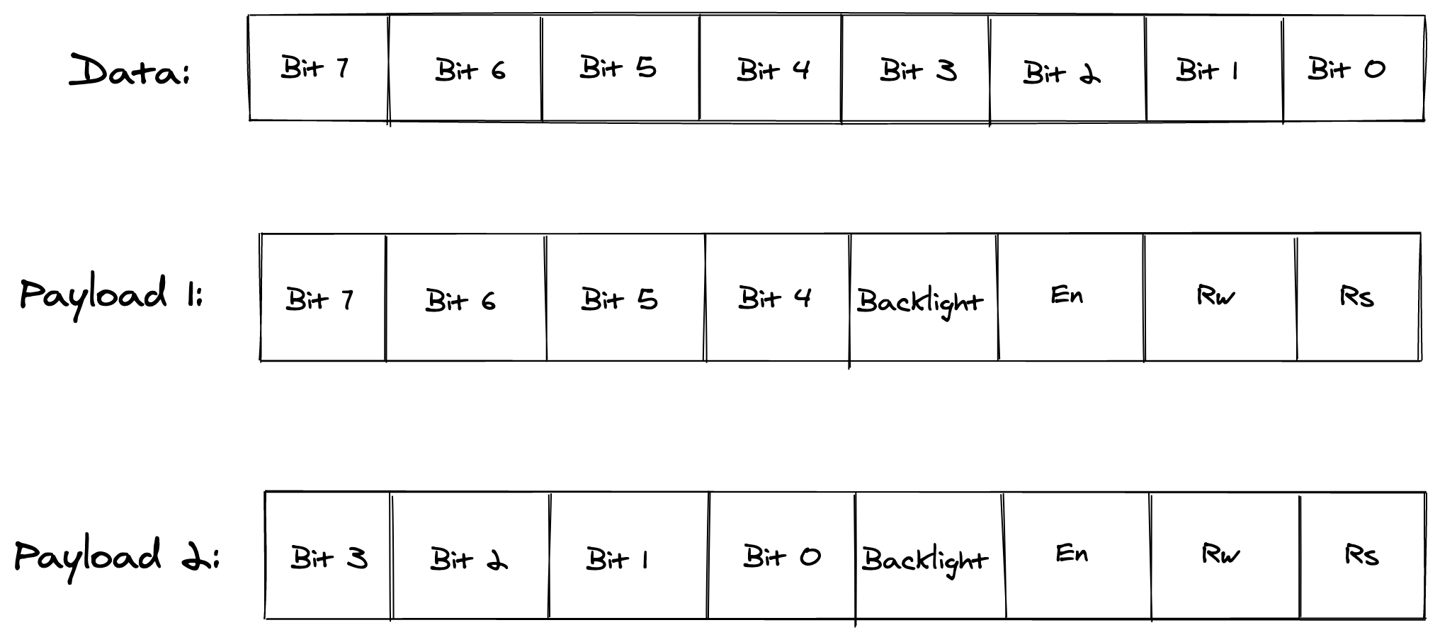
The Hitachi HD44780 LCD controller is able to communicate in 8-bit or 4-bit mode. In a “normal” setup, 16 pins are used to communicate with the controller, where 8 of those pins are for instruction data (this does not include the R/W, RS, En, and possible backlight bits). In 4-bit mode, there are only 4 pins for data, therefore the data is sent in two batches with the four most significant bits sent first and the four remaining bits sent after.
You may notice the problem. I2C only has one data wire, how’s it supposed to write data to a controller that usually require more than ten connections? First, I2C has to send the data serially (this results in a higher latency, which is the main downside of using I2C with LCDs). Second, the I2C implementation requires the usage of 4-bit mode; I2C communications already batch the data into 8-bit chunks, but we can’t use all 8-bits for an instruction as we need to reserve bits for R/W, RS, En, and backlight flags. Therefore, the four most significant bits of each I2C payload will be the instruction (either the high or low four bits of the instruction) and the remaning four bits will be for the flags.
For the purpose of this example, we’ll need to be able to send instructions and data, and we’ll just always assume that we want the LCD backlight on.
use stm32f3xx_hal::{self, delay, pac, i2c, stm32};

...

const LCD_ADDRESS: u8 = 0x27;
const En: u8 = 0x04;
const Backlight: u8 = 0x08;

...

type Pins = (stm32f3xx_hal::gpio::gpiob::PB6<stm32f3xx_hal::gpio::AF4>, stm32f3xx_hal::gpio::gpiob::PB7<stm32f3xx_hal::gpio::AF4>);

fn write4bits(i2c: &mut i2c::I2c<stm32::I2C1, Pins>, data: u8) {
    i2c.write(LCD_ADDRESS, &[data | En | Backlight]);
    delay_ms(1);
    i2c.write(LCD_ADDRESS, &[Backlight]);
    delay_ms(5);
}

fn send(i2c: &mut i2c::I2c<stm32::I2C1, Pins>, data: u8, mode: u8) {
    let high_bits: u8 = data & 0xf0;
    let low_bits: u8 = (data << 4) & 0xf0;
    write4bits(i2c, high_bits | mode);
    write4bits(i2c, low_bits | mode);
}

fn write(i2c: &mut i2c::I2c<stm32::I2C1, Pins>, data: u8) {
    send(i2c, data, 0x01);
}

fn command(i2c: &mut i2c::I2c<stm32::I2C1, Pins>, data: u8) {
    send(i2c, data, 0x00);
}
Let’s go through each function. The main difference between write and command is the setting of the Register Select (RS) bit, where a value of 1 says we’re sending a write (put stuff on the screen!) or a command (set some configuration). The send function just splits our data into two most/least significant bit chunks and makes two calls to write to the device.
Now we get to write4bits, which I’ve come up with upon reading through some other I2C implementations and trial and error. To be completely honest, this is probably least documented part I ran into while researching this post; it seems that there is some odd tribal knowledge around how this specific part of the I2C implementation works for this LCD. Nevertheless, I’ll go through what I’ve found to work.
i2c.write(LCD_ADDRESS, &[data | En | Backlight]);
Here we’re using the write method on the I2C peripheral we initialized earlier. LCD_ADDRESS is the address of the I2C slave we want to communicate with on the bus (0x27). Because we can actually send as many payloads to the address we specify without giving up control of the bus, this method takes a reference to an array of u8s, but we’ll only be sending one. payload at a time. We’re sending our four bits of data in the four most significant bits of the payload, we enable the Enable (En) bit to tell the controller “hey, this is data that you should be receiving,” and we keep the backlight on.
i2c.write(LCD_ADDRESS, &[Backlight]);
Even if we’ve only transmitted half of the intended instruction, we do another write to unset the En bit (we want the En bit to be 0, but we still want the backlight on). I’m not really sure what the purpose of this is (maybe it’s to notify the conroller that we just sent data?), but I haven’t been able to get this working without unsetting the En bit. All implementations I’ve seen for this LCD (I2C or not) include this “pulsing” of the enable bit.
LCD initialization
Now we’re ready to start sending data to the LCD! First, we need to properly initialize it; the LCD is it’s own microcontroller, so we don’t really know what state it’s in when we boot it up. Luckily, the initialization procedure is pretty easy, we initially just force the microcontroller into 8-bit mode (even though we only have 4 bits for instruction per I2C payload, this is fine).
    write4bits(&mut i2c, 0x03 << 4); // Set to 8-bit mode
    delay_ms(5);
    write4bits(&mut i2c, 0x03 << 4); // Set to 8-bit mode
    delay_ms(5);
    write4bits(&mut i2c, 0x03 << 4); // Set to 8-bit mode
    delay_ms(5);
We just send the instruction to set the controller into 8-bit mode three times. We do this because the microcontroller can be in one of three states:
- It’s already in 8-bit mode
- It’s in 4-bit mode, waiting for a new instruction
- It’s in 4-bit mode, but it’s waiting for the last 4-bits of a previously sent instruction
If it’s already in 8-bit mode, we keep telling the controller to stay in 8-bit mode, so this is all good. If the controller is in 4-bit mode but is waiting for a new instruction, the first two instructions will be taken together and set the controller to 8-bit mode.
In the last case, where the controller is waiting for the last 4 bits of a partially transmitted instruction, sending the first write will result in some unknown instruction; the controller could still be in 4-bit or 8-bit mode at this point. If the controller is still in 4-bit mode after the first instruction, the last two instructions will set it to 8-bit mode, and if the controller happened to switch to 8-bit mode after the first instruction, the last two instructions will keep it in 8-bit mode.
After all that, we know that the controller is in 8-bit mode, and we now set the controller to 4-bit mode.
write4bits(&mut i2c, 0x02 << 4); // Set to 4-bit mode (while in 8-bit mode)
We only need to send one instruction to put the controller in 4-bit mode as we are currently in 8-bit mode. At this point, we just need to configure the controller to our specific use case! I’ll paste my remaining initialization code below, but I won’t go into it as it’s dependent upon what you want!
    // My controller has two rows
    // and each input is 5x8 pixels
    command(
        &mut i2c,
        0x20 as u8 | // Function set command
        0x00 as u8 | // 5x8 display
        0x08 as u8   // Two line display
    );

    // Turns display on,
    // shows the cursor under the current input,
    // the current input blinks
    command(
        &mut i2c,
        0x08 as u8 | // Display control command
        0x04 as u8 | // Display on
        0x02 as u8 | // Cursor on
        0x01 as u8   // Blink on
    );

    // Clears the display and returns cursor
    // to top left position
    command(
        &mut i2c,
        0x01 as u8 // Clear display
    );

    // Specifies that the cursor moves to the
    // right after each write
    command(
        &mut i2c,
        0x04 as u8 | // Entry mode command
        0x02 as u8   // Entry right
    );
Hello, World!
Now we’re ready to print “Hello, world!”
let hello: &'static str = "Hello, World!";
for c in hello.chars() {
    write(&mut i2c, c as u8);
}
Yup, that’s it. We did all the heavy lifting with the initialization, if only it could have been this easy all along…